| Code | Name | Description |
|---|---|---|
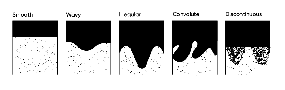
| S | Smooth | The boundary surface is a plane with few or no irregularities and usually occurs at the same depth across the profile face. |
| W | Wavy | The boundary surface has broad, shallow, relatively regular pockets and none deeper than they are wide. |
| I | Irregular | The boundary surface has pockets that are deeper than they are wide but not recurved. |
| C | Convolute | The boundary surface has pockets that are deeper than they are wide and, in parts, recurved. |
| D | Discontinuous | The boundary is discontinuous, usually due to external disturbance. |
| N | Not observed | The lower horizon boundary could not be observed. |
11 Soil profile
A soil horizon is a distinct zone that can be identified within a soil profile, usually but not always parallel to the land surface. Soil horizons are distinguished by differences in texture, stoniness, structure, colour, consistence or other soil properties, as described in the following sections.
Delineated horizons should ideally represent depth intervals over which important soil attributes change minimally, although some short-range internal variation may occur. Conversely, the horizon boundaries should represent depth intervals over which there is a relatively high rate of change of important soil properties.
Soil horizons emerge from a complex interaction of differentiating and homogenising forces, the detailed discussion of which is beyond the scope of this handbook. See Hartemink et al. (2020) and Palmer et al. (2025) for further reading.
Soil horizons are commonly grouped into two major zones: the topsoil, where biological activity is elevated and new additions of soil parent material may be received, and the subsoil, a zone where materials are both received from above and leached to below, as well as where weathering processes are concentrated, generating new soil minerals. Below these zones, collectively called the ‘solum’, a ‘subsolum’ of variably weathered soil parent materials continues, often for many metres. These materials can include paleosols buried by subsequent depositional events, unconsolidated deposits that have not been subject to strong weathering, and rocks weathering in place.
In New Zealand many landscapes are underlain by sedimentary rocks that were not strongly consolidated before becoming exposed to weathering forces, so the boundary between the solum and the subsolum can be particularly difficult to define.
While this handbook focuses on describing the solum, the subsolum, when encountered, should be described as well. Subsolum materials play a key role in deep drainage, groundwater recharge, slope stability, and ecological support (Juilleret et al. 2016). ‘Horizon’ boundaries within the subsolum will most commonly relate to lithological or depositional discontinuities.
11.1 Defining the soil surface
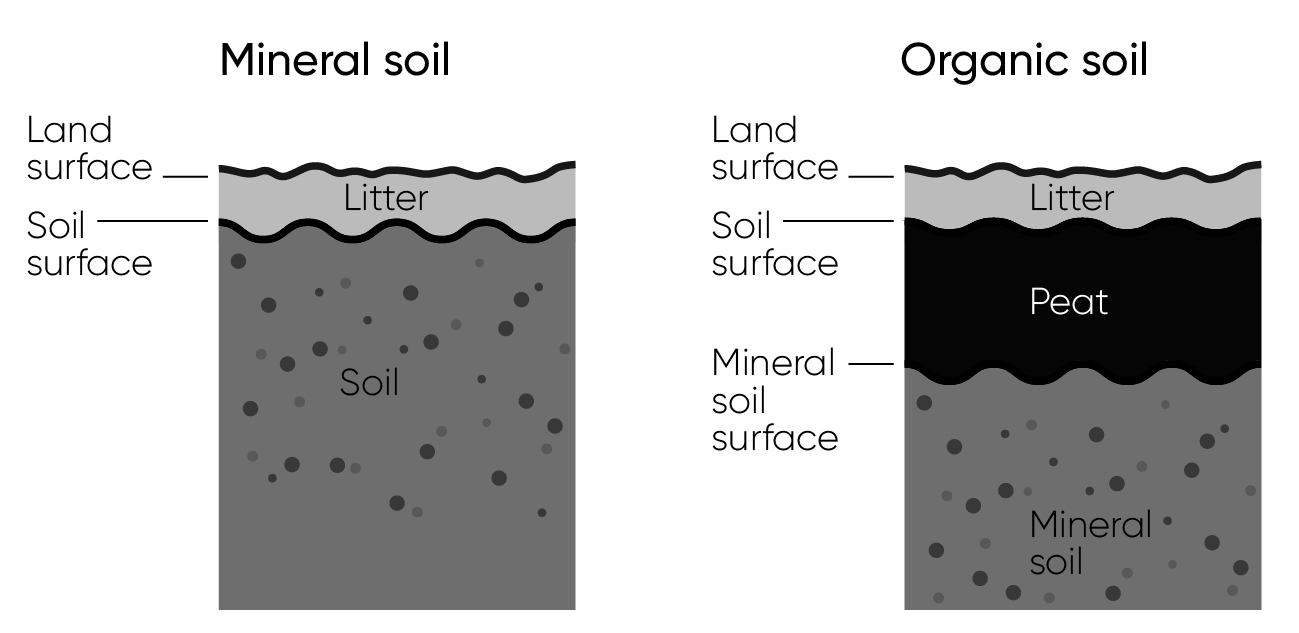
The soil surface has a slightly more restrictive definition than the land surface. The soil surface begins below the layer of fresh leaf litter or small living plants, and at the top of organic soil materials such as decomposing litter or peat. The mineral soil surface is further restricted, identified as the top of the first horizon that is dominated by mineral soil material. Horizon depths are defined with reference to the soil surface overall, so only fresh litter and/or small plants should be scraped back before measuring.
11.2 Boundary depth
Horizon depths are recorded starting from the soil surface at 0 cm and working downwards cumulatively.
When examining single small cores or auger points (see Table 9.3, type A, C1 and perhaps C2), record the observable lower boundary depths of each horizon from the soil surface in whole centimetres (e.g. 28 cm).
Where a wider exposure (see Table 9.3, type E, P1, P2) or multiple undisturbed cores are available and greater detail is desired, the surveyor may choose to record lower boundary depths as a median and range, again in whole centimetres (e.g. 28 cm (27–29)). At least five measurements should contribute to such an assessment. This practice can be useful for describing irregular, convolute or discontinuous horizons (Section 11.3).
Measure boundaries to and from the midpoint of each horizon transition zone (see Section 11.4). Where depths are correctly measured, horizon thicknesses can be calculated after fieldwork.
Important 11.1: Defining horizons on steep slopes
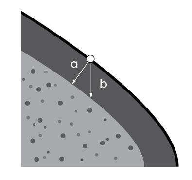
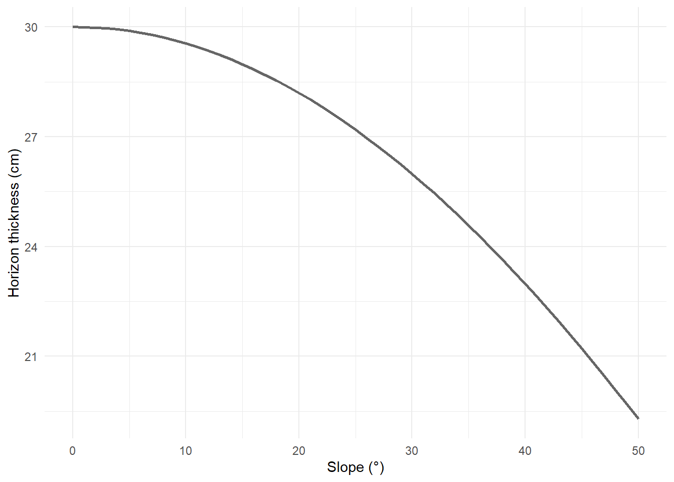
On steeper slopes, measuring horizons from vertical exposures can exaggerate horizon thicknesses, because the soil horizons mantle the landscape perpendicular to the sloping surface (Prietzel and Wiesmeier 2019). This starts to become noticeable at slopes > 10°, and progressively becomes more important, especially when calculating volumetric stocks of soil components. Figure 11.2 shows the relative difference between measuring perpendicular and measuring vertically, and Figure 11.3 charts the degree of exaggeration with increasing slope.
Where depths are measured perpendicular to the surface no adjustment needs to be made. To adjust vertically measured horizon depths to correct for slope, apply the formula \(depth × cos(slope)\). Supply depth in centimetres and slope in radians. Slopes measured in degrees can be converted to radians using the formula \((slope × \pi) ÷ 180\). If this correction is made, clearly indicate this is the profile description record to prevent the horizon depths from being adjusted any further.
11.3 Boundary shape
Horizon boundary shape can only be observed on wider exposures (see Table 9.3, type E, P1, P2). Record using one of the options in Table 11.1. Note that the boundary shape is associated with the lower boundary of any given horizon, so the lowest horizon described on a profile may have an undefined boundary shape if profile exposure stopped early (Section 9.2.8). In that case, use code N.
11.4 Boundary distinctness
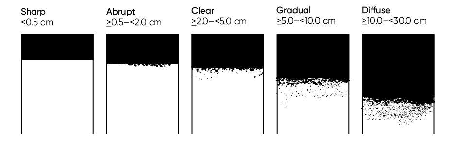
Horizon boundaries mark changes in soil properties over short vertical distances. The distinctness is variable, from very sudden to gradual, and can signify particular soil characteristics (e.g. a change in parent material). Horizon boundary distinctness is used when classifying soils.
Measure the distinctness of a horizon’s lower boundary in terms of its width. Report a median and range in 0.1 cm increments (e.g. 2.0 cm ± 0.5 cm). For rapid assessment, horizon boundary distinctness can be recorded using one of the options in Table 11.2.
| Code | Name | Description |
|---|---|---|
| S | Sharp | < 0.5 cm |
| A | Abrupt | ≥0.5 to <2.0 cm |
| C | Clear | ≥2.0 to <5.0 cm |
| G | Gradual | ≥5.0 to <10.0 cm |
| D | Diffuse | ≥10 to <30.0 cm |
| N | Not observed | The lower horizon boundary could not be observed. |
Where a transition is thicker than 30 cm it should be defined as a new horizon. Use transitional horizon names as needed (see Section 18.5).
11.5 Infill features
Infill features are interruptions to the horizonation pattern caused by relatively recent biological or physical disturbances. Infill features are large enough such that they can usually only be clearly observed at exposures or large pit faces. The interruption may extend across several horizons, and the infilled material may be from adjacent horizon(s) or comprise reworked material from the affected horizon(s). Where infill features are present, for each affected horizon record the type using the options in Table 11.3 and the infill material using the options in Table 11.4.
For example: use C T for infilled shrink–swell cracks.
Open subsurface voids should be described as per Section 12.4.1, and open surface cracks as per Section 10.6.
| Code | Name | Description |
|---|---|---|
| C | Crack | Infilled surface crack caused by shrink–swell clay movement |
| T | Tunnel | Infilled animal burrow ≥20 mm diameter |
| B | Burrow | Infilled animal burrow <20 mm diameter |
| R | Root | Infilled root channel |
| D | Drain | Infilled mole drain or similar deep-tillage feature |
| Code | Name | Description |
|---|---|---|
| T | Topsoil | Infilled by topsoil material (in non-topsoil horizons) |
| S | Subsoil | Infilled by subsoil material (in topsoil or regolith horizons) |
| O | Organic | Infilled by organic material |
| L | Local | Infilled by reworked material from the same horizon |
| M | Mixed | Infilled by mixed materials from multiple horizons |
| U | Unknown | Infill material cannot be determined with confidence |
11.6 Soil moisture status
Report soil moisture status for each horizon at the time of observation. This parameter supports assessments of drainage and permeability, and contextualises consistence tests.
| Code | Name |
Behaviour of the fine-earth fraction
|
|||
|---|---|---|---|---|---|
| ≥80% sand | <80% sand <18% clay |
≥18% clay <35% clay |
≥35% Clay | ||
| D | Dry | Loose, single grain | Loose | Easily broken down to powder | Hard, baked, cracked |
| T | Moderately moist | Will not form a ball | Forms weak ball, breaks easily | Forms a ball, very pliable | Forms a ball, somewhat pliable |
| M | Moist | Forms very weak ball | Forms weak ball, breaks easily | Forms a ball, very pliable | Easily forms a ball |
| W | Wet | Fluid, non-plastic, non-sticky | Slightly fluid, slightly plastic | Deformable, plastic | Semi-deformable, very plastic |
| S | Saturated | Water films visible, or below water table | |||
| Source: adapted from Griffiths (1985). | |||||
11.7 Depth to free water
Depth to free water can be determined from the depth to the uppermost S saturated horizon (Table 11.5), or can be recorded directly, in whole centimetres. Depending on the soil’s transmissivity, the water-table may also become evident by the pit or core filling with water. In this case, wait for the water level to stabilise before measuring.
- Use a code from Table 11.6 to record the water-table’s position in the profile (or its absence).
- Where the water-table is present, record its depth above or below the soil surface in whole centimetres. Do not record negative numbers to signify a water-table above the surface.
- If the water-table is exactly at the soil surface, record A 0.
For example: use B 80 for a profile saturated below 80 cm depth; A 1 for a saturated and barely-walkable peat.
| Code | Name | Description |
|---|---|---|
| NA | Not applicable | Water-table not encountered |
| B | Below | Water-table observed below the soil surface |
| A | Above | Water-table observed at or above the soil surface |
11.8 Parent materials
Information about the lithology, origin, and weathering degree of the soil parent materials is essential for accurate classification and helps contextualise analytical data.
11.8.1 Lithology
For rapid description, dominant lithology is recorded once for the profile (Section 9.3.2). Where the subsolum is encountered, record its lithology (Section 12.5.1) separately if it differs from the overlying material.
For example: use SAFT, ANDS for a mix of eroded sedimentary rocks and volcanic ash.
For routine description, the lithology of the fine-earth fraction (mineral particles <2 mm) is recorded separately for each soil horizon, as are any rock fragments observed in each horizon (see also Section 12.2.1). In the subsolum, each distinct layer observed should have its lithology captured separately. In all cases, use the codes in Table 4.1 and record only the dominant lithologies present.
For a detailed description, a more complete list of lithologies may be defined for each mineral component.
11.8.2 Origin
Parent material origin, or mode of emplacement, describes how soil parent materials have arrived at the point of observation. Multiple modes may have operated in different parts of the soil profile. For residual soil materials, the origin is recorded as the last major formation process that left the materials in a place where they could start weathering into soil.
For rapid assessment, dominant parent material origin is recorded once for the profile, using up to two codes from Table 11.7. For routine assessment, record one parent material origin code per soil horizon using the codes in Table 11.7. At the horizon level, the An (Anthropic) class can be subdivided by origin using the codes in Table 11.8.
For example: use Ann for a fill pad in a residential housing development.
| Code | Name | Description |
|---|---|---|
| Transported | ||
| An | Anthropic | Deposits made by the direct actions of humans, including truncation, mixing, or deposition. |
| Cl | Colluvium | Unconsolidated and unsorted, usually weathered soil and rock material deposited on lower slopes, transported primarily by gravity assisted by water. These deposits may comprise slow accumulations or result from sudden slope failures. |
| Db | Debris avalanche | Deposits derived from the large-scale collapse of unstable slopes of stratovolcanoes, forming mounds and hummocky ground that can be unconsolidated or heat-welded. |
| Fl | Alluvium | Sediments that have been deposited by streams, rivers and other running water. |
| Gl | Glacial till | Poorly stratified, poorly sorted rock fragments, sand and mud, surface or near-surface deposits resulting from the transportation by and deposition from ice or meltwater from beneath or in close proximity to glacial ice. |
| Lc | Lacustrine | Formed in and around lake bed deposits; comprises extremely fine sediment deposited under very low flow and usually freshwater conditions. |
| Mr | Marine | Unconsolidated sediments saturated by brackish or saline water. |
| Lh | Lahar | A flow of heterogeneous volcaniclastic material mixed with water and deposited rapidly in river valleys associated with stratovolcanoes. Lahars may be triggered by volcanic eruption or by cone collapse in response to oversteepening. |
| Tp | Tephra | Unconsolidated primary pyroclastic products of explosive volcanic eruptions encompassing all grain sizes (ash, lapilli and larger) and lithologic compositions. Both airfall and non-welded pyroclastic flow deposits are included. |
| Lo | Loess | A blanket deposit of silt-sized particles (0.002–0.06 mm diameter); usually carried by wind from dry riverbeds or outwash plains during glacial and post-glacial periods. |
| Sa | Aeolian sand | Wind-deposited sand-sized particles (0.05–2.0 mm diameter, i.e. dune sand). |
| Sf | Solifluction | Unconsolidated, unsorted, usually weathered soil and rock material mantling hillslopes and derived from slow, viscous, gravity-driven downslope movement of waterlogged soil and material in terrains underlain by frozen soil or permafrost, either now or in the past. |
| Residual | ||
| Ex | Extruded rock | Volcanic rocks that were emplaced on the land surface in a molten state |
| In | Intruded rock | Plutonic rocks that were emplaced beneath the land surface in a molten state |
| Rx | Indurated rock | Uplifted rocks with strong sedimentary induration and/or metamorphosis |
| Rw | Non-indurated rock | Uplifted sedimentary rocks with weak to moderate induration and no metamorphosis |
| Organic | ||
| Li | Litter | Plant material decomposing under intermittently wet and dry conditions |
| Pt | Peat | Plant material decomposing under saturated conditions |
| Other | ||
| Uk | Unknown | Origin cannot be determined with certainty. |
| Code | Name | Description |
|---|---|---|
| m | Historic Māori | Soil modifications resulting from Māori cultural practices dating from Polynesian arrival in New Zealand, particularly agricultural practices |
| p | Historic Pākehā | Soil modifications dating from Pākehā (non-Māori) arrival in New Zealand up to modern times (e.g. non-mechanised European agricultural and mining practices) |
| n | Modern | Soil modifications resulting from modern mechanised agricultural practices, other land alteration practices (e.g. mining, terracing in urban environments) and/or addition of industrially produced materials to the soil (e.g. plastics) |
11.8.3 Weathering
The effects of weathering and pedogenesis vary down-profile (usually, but not always, decreasing with depth). Horizons that have experienced limited weathering may require specific descriptors. For example, texture (Section 14.3) cannot usually be determined on paralithic material, but bedding (Section 12.5.3) may need to be described, so the need for these should be assessed early in the description process. Use the guidance in Table 11.9 to clearly identify the solum, as well as any subsolum materials encountered. The weathering status of rock material specifically may be assessed using the schema in Section 12.2.1.2.
| Code | Name | Description |
| So | Soil material | Horizon characteristics include any of:
a lack of residual geogenic structure. |
| Rg | Regolithic material | The horizon:
|
| Sr | Saprolithic material | The horizon:
Roots may be present in the matrix and/or along remnant geogenic features. |
| Pr | Paralithic material | The horizon:
|
| Rr | Lithic material | The horizon:
|