Appendix C — Observing and sampling soils
C.1 Exposing the profile
The following are general procedures; they may need to be adapted to specific locations. Further discussion of these methods may be found in Ryan and Wilson (2008), Heck (2017) and IUSS Working Group WRB (2022).
C.1.1 Digging a standard pit
- Pre-screen potential excavations for buried infrastructure. Use ‘dial before you dig’ services and ideally a pipe/cable locator. On farms away from urban services, talk to the landholder about the locations of water supply pipes, gas-line easements and similar.
- On flat land, choose a pit orientation that will create optimal lighting conditions on the main face. On sloping land above ~10 degrees, orient the pit against the slope to minimise effort and keep the pit structure safe.
- Excavate a large enough area to work in, usually 0.5–1.0 m wide.
- Work towards a target depth of 1 m at the main face (or at the very least, the top of the B horizon), leaving steps for access and benching side walls to minimise collapse risk.
- Place spoil to one side on a tarpaulin, far enough back from the edge that it won’t fall back in. Don’t place spoil uphill.
- Ideally, separate top and subsoil for refilling.
- Avoid compressing or disturbing the surface above the main face.
- If it is not safe to dig to the target depth, use an auger to extract soil materials beyond the safe depth.
- Always stop excavating at the water table for safety reasons.
- Clean the main face and prepare it as described for exposures (Section C.1.3).
- Proceed with soil profile description and sampling.
- After describing, refill the pit, tamping down spoil to re-create the former surface as closely as possible.
C.1.2 Digging a minimal pit
Smaller pits lack the safety risks of standard pits, but locations should still be pre-screened for buried infrastructure (see Section C.1.1).
- On flat land, choose a pit orientation that will create optimal lighting conditions on the main face. On sloping land above ~10°, orient the pit against the slope to minimise effort and keep the pit structure safe.
- Excavate a small pit ~1 spade-width wide and 3–4 long, to at least ~0.6 m deep. Ideally the top 5–10 cm of B horizon should be exposed, so deepen the pit slightly if necessary. Place spoil to one side on a tarpaulin, separating the topsoil and subsoil.
- Where texture and moisture conditions allow: Using the spade, gently excavate a ‘slice’ of the back pit face 5–10 cm thick. Remove the profile slices in sections, laying them out on a tarpaulin or mat.
- If necessary, use a hand auger to pull out the remaining profile to 1.0 m, continuing to lay the samples out below the pit face slices.
- Clean up the pit and photograph the inside, with a suitable measuring tape in place. Take horizon depths from the pit face in preference to the extracted profile as they will be more accurate.
- Place a suitable measuring tape alongside the extracted profile and take photographs.
- Proceed with description and sampling.
- Refill the pit, restoring the former ground surface as closely as possible.
C.1.3 Cleaning an exposure
- Locate a part of the exposure that is safely accessible. Exposures can change rapidly over short distances, so consider the landscape/landform and which section(s) of the exposure might be most representative.
- Trim back or clear overhanging vegetation.
- Use a spade to scrape back at least the first few centimetres of soil, revealing a fresh face approximately 40–50 cm wide. Try to create a roughly vertical face; this may involve excavating ‘in’ to the exposure surface.
- If the exposure is less than 1 m tall, some minor excavation may be required to expose the profile to sufficient depth.
- Use a smaller hand tool to finish smoothing back the face (work across rather than down and avoid smearing), and then optionally use it to ‘pick out’ the right-hand half of the face in a way that reveals the soil structure in situ.
- Clean off the lower parts of the exposure face, which may have become coated with material from upper horizons. This is especially important when sampling.
- Anchor a pit tape on the left side of the profile, optionally also pinning it at the base.
- If the profile is partly or fully dry, spray it down lightly with water to bring up the colours consistently across the whole face.
- Photograph the full profile and then zoom in on ~30 cm sections. Optionally, mark the horizon boundaries with pins and take a second whole-profile photo.
- Proceed with the soil description and sampling.
- After describing, clean up any spoil, either infilling excavation or sweeping it back out of any adjacent drains.
C.1.4 Extracting an undisturbed core
This procedure refers to extracting cores of 30–100 cm length and 30–70 mm diameter for profile description. See Section C.3.2 for extraction of short intact cores for soil physics analyses.
The device used to insert the sampling tube can be mechanical (e.g. post-hole driver or vehicle-mounted drilling rig) or manual (post hole driver, sledgehammer). These instructions are generic to the insertion device and sampling tube system in use. Instructions are not given for the use of screw augers as they do not extract a useable sample for profile morphology description.
- Lay out a tarpaulin, mat or 100 mm diameter plastic half-pipe to hold the extracted soil.
- If working in a new area, conduct a test auger as per Section C.1.5 to assess the soil conditions. Excessive moisture or high stone content may make coring difficult, and some knowledge of the soil texture and consistency will help choose an appropriate cutting tip size for the sampling tube.
- Scrape back any litter layer and trim grasses from around the area to be cored.
- Insert the sampling tube using the device of choice.
- If possible, insert a metal bar into the top of the sampling tube and twist it in place to break the soil core’s connection with the underlying material.
- If possible, seal the top of the sampling tube to create a slight vacuum.
- Use a foot jack or similar extraction device to carefully remove the sampling tube from the ground. Mark the core hole location clearly.
- Slide the core sample back out of the top of the sampling tube (after removing the seal, if applicable). If the sample does not slide out easily under its own weight, options for extraction include:
- Tapping on the side of the sampling tube with a rubber mallet
- Shaking the tube, vertically (keep a hand over the ‘exit’ while doing so)
- Tapping the ‘exit’ end firmly against a block of timber
- Pushing the sample through the tube from the cutting-tip end with a wooden dowel.
Exercise these options with caution and patience to avoid plugging up the tube. Adjusting the cutting tip size and/or extracting the core in 30–40 cm sections can also be helpful.
- Once the soil core is extracted, split it open lengthwise, pulling the sections apart gently rather than cutting all the way through.
- Describe the extracted profile, allowing for limitations in the size of features visible (e.g. large structural units may not be appreciable).
- Refill the core hole as far as possible. Use a spade to collapse the top of the hole and recreate a firm surface. This is especially important in paddocks containing livestock.
C.1.5 Hand augering
- Lay out a tarpaulin or mat to hold the extracted soil.
- Use a spade to remove the first 10–20 cm of profile and/or an overlying litter layer. This allows for accurate determination of surface structure, and avoids having to auger through dense surface plant matter (e.g. pasture grasses).
- Auger to depth, taking care to remove the soil in small sections without overfilling the auger head.
- Lay the extracted soil materials out on a tarpaulin, half-pipe or sampling board with reference to a suitable measuring tape.
- Check the hole depth with a tape measure every 3–5 extractions, adjusting the extracted soil to match the depth achieved.
- Pay attention to the ‘feel’ of the auger; this may change noticeably as new horizons are encountered or the water table is reached. You may need to adjust the amount of downward pressure in response.
- Describe the extracted profile as far as possible, given that parameters like structure may not be observable using this method.
- Refill the auger hole as far as possible. Use a spade to collapse the top of the hole and recreate a firm surface. This is especially important in paddocks containing livestock.
C.2 Observing the profile
The way in which a soil profile description is completed will depend on the level of detail required, and the number of people involved. The following comprises general advice on efficient workflows.
Firstly, record reference and setting data for the site (Section 9.2, Section 9.3), and take landscape and surface photographs (see Section B.3). Secondly, record data about the soil surface within the site bounds (Chapter 10). This may be done by one worker while other(s) expose the profile (Section C.1).
Once a suitable profile has been exposed, examine it initially as a whole.
- Position a measuring tape next to the profile face or core, with the 0 cm mark carefully aligned to the soil surface (Section 11.1). Photograph the profile as a whole and in sections (see Section B.3).
- Identify and mark the lower boundary of each observable horizon (Section 11.2). Keep in mind that these can be changed as the description proceeds. Where observable, record any relevant information about infill features (Section 11.5).
- Record the moisture status of each horizon (Section 11.6). Doing this early in the description process is more accurate to field conditions, as profiles and cores can dry rapidly in the sun.
- Record the depth to free water, or its absence (Section 11.7).
- Record the dominant profile lithology (or lithologies, Section 11.8.1) and parent material origin (Section 11.8.3).
- If the observable profile extends into the subsolum, distinguish the observable zones of weathering (Section 11.8.2).
- On larger exposure faces, examine the spatial distribution of live roots throughout the profile, and look for any obvious evidence of rooting depth restrictions (Section 19.3).
- Extract small samples from each horizon for consistence and field tests. Set them aside in a way that protects them from the elements and minimises the possibility of mixing samples up, e.g. in marked containers.
Now move on to examining the horizons. It is usually more efficient to describe each parameter in turn down the profile (especially if multiple people are working together), but learners may find it easier to describe one horizon at a time. In cases where a limited volume of soil materials are available for examination, it may be prudent to record the more ‘hands off’ parameters first and then move on to those that require more direct physical disturbance. Where field time is limited, prioritise colour and colour patterns, structure, texture, and consistence, as they are the most important for classification.
- Describe the nature of the horizon boundaries and transition zones (Section 11.3, Section 11.4).
- Record the matrix colours and any patterns, if present (Section 13.1).
- Observe the horizon in situ and note the degree of structural development (Section 12.1.2), its mode of origin (Section 12.1.1), and the relationship between peds and voids (Section 12.4.1), where those have developed. More detailed examination of root density, positioning and distribution can follow (Section 12.3), as well as pores (at least in apedal massive soil materials - Section 12.4.2). Pans may also be identifiable at this stage (Section 15.3).
- Extract a hand-sized sample, assess and describe structure according to Section 12.1.5. Where peds have developed, record any coatings or stress features visible on ped faces (Section 15.2, Section 15.4), and assess their porosity (Section 12.4.2). Note any concentrations developed among or within the peds, or within the soil mass (Section 15.1). Record information about any fragments present (Section 12.2).
- Set aside materials >2 mm from the sample, and determine the fine earth texture (Section 14.2). Modify the texture code as needed to account for rock fragments and organic matter (Section 14.3), and estimate clay and sand percentages.
- Using the samples set aside earlier, complete any necessary consistence and/or field tests (Chapter 16, Chapter 17).
- Where subsolum layers are available for description, record any relevant additional parameters (e.g. rock weathering, bedding, fracturing; see Section 12.5).
- If lithology and parent material origin are observed to vary significantly down-profile, record these parameters per horizon (Section 11.8.1, Section 11.8.3).
- If horizon boundaries need to be adjusted, sufficient information should now be available to support amendments.
- Lastly, review the description against the requirements in Section B.4 and Chapter 20 and check that no critical information is missing.
With the horizon parameters described, the final steps are interpretive.
- Apply horizon notation to the profile (Chapter 18), and determine drainage and permeability ratings on a per-horizon basis (Section 19.1.1, Section 19.2.1).
- Summarise drainage and permeability at the profile level (Section 19.1.2, Section 19.2.2).
- If any further root barriers were identified during horizon description, record these (Section 19.3).
- Classify the profile according to the New Zealand Soil Classification.
C.3 Sampling the profile
Profiles are sampled for laboratory analysis to quantify and extend data recorded in the field. Undisturbed samples are required for soil physical analyses, and require specific equipment.
C.3.1 Sampling for chemical analysis
The following method is for sampling from a pit or exposure face for full characterisation of soil chemistry and mineralogy. These samples may be extracted next to hand-carved cores for soil physics, as per Section C.3.2.1.
Sample volumes should be tailored to the needs of the planned analyses, including any desire for archiving material for future use (0.5 kg is a sensible minimum). Sample volumes may need to be adjusted upwards to account for rock fragments >2 mm and water content.
- Before sampling the topsoil, trim back surface vegetation with a knife or scissors.
- Aim to sample continuously and sequentially down the exposed profile face, widening or deepening the sampled zone as needed to extract sufficient volume from thinner horizons.
- Aim to take at least one sample from each horizon; otherwise, subdivide thicker horizons and sample in 10–30 cm vertical increments.
- Avoid sampling across thinner horizon boundaries, adjusting to avoid wavy or irregular transition zones. Transition zones >5 cm thick may be sampled separately if desired.
- Where large infill features are present, these may be avoided in favour of sampling the material that comprises the majority of the horizon. However, there is no need to attempt to separate intermixed materials in a transitional horizon (see Section 18.2.6).
- Samples should be collected into polythene bags or sealed containers with clear labels including the site identifier, depth increment, and date. Samples should be stored in a rigid, insulated container to prevent damage or exposure to temperature extremes.
- Communicate any specific soil features relevant to sample processing and analyses to the laboratory, e.g. the presence of allophanic soil materials, rock fragments, or pedogenic features like carbonate nodules.
Similar sampling procedures can be completed using relatively undisturbed cores (Section C.1.4) but multiple cores may be required to gather enough sample volume from each horizon.
C.3.2 Sampling for physical analysis
Soil physical analyses require minimally disturbed soil samples of a known volume. Near the surface, samples can be taken while progressively excavating a minimal pit - but deeper extraction will require access to an exposure or standard pit face.
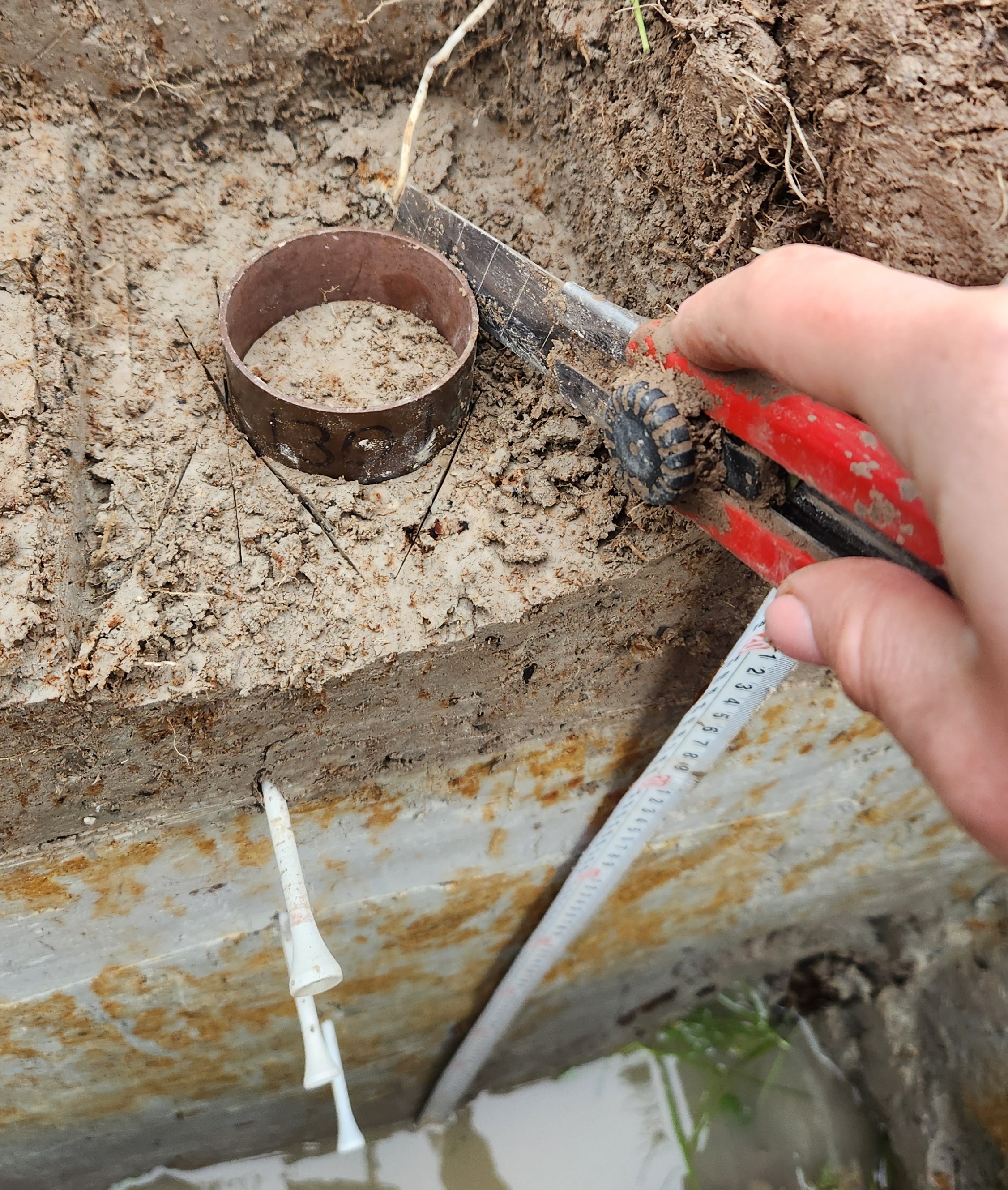
C.3.2.1 Hand-carved rings
This method may be applied to a wide variety of soils but performs best with moist, non-stony, loamy or silty textures.
Equipment
- Pit-digging tools
- Measuring tape (1–3 m)
- Metal sampling rings (usually ~50–100 mm diameter and 30–80 mm high, with a sharp lower edge). These rings must be numbered, weighed and measured accurately prior to use.
- Vaseline for lining the interior of the sampling ring (hydraulic conductivity samples only)
- Spacer that fits over the sampling rings
- Wooden block larger than the sampling ring diameter
- Cling film
- Snap-blade knife and thin metal paint-scraper or spatula
- Scissors or secateurs for trimming surface vegetation
- Permanent markers
- Data recording sheet (or spreadsheet)
Method
- Locate the point to be sampled. For sampling the surface or to shallow depths (e.g. 30 cm), dig a small pit ~50 x 30 cm to the target depth. For deeper sampling, dig a full pit (Section C.1.1) at least 80 cm wide and long enough that a worker can comfortably crouch to reach the lowest target depth.
- Select the pit face from which samples will be taken. From the surface above the face, remove any litter, and carefully trim any small vegetation back to the land surface without pulling out roots. Clear an area ~20 cm wide and deep.
- Place a measuring tape against the pit face and place markers at target depths for sampling. The markers should specify where the top of each sampling ring will sit when it is fully inserted into the soil. For sampling the centre of a depth range (either a horizon or set increment), calculate each target depth as \(increment\ midpoint - (0.5 × ring\ height)\) (all units in centimetres).
- If sampling the surface, no further preparation is required. If sampling begins at a depth below the surface, use a sharp blade to carve out the soil from the surface down to this depth, creating a level pedestal at least twice as wide as the sampling ring. Allow enough space for the sampling ring to be set back at least 5 cm from the pit face.
- Place a numbered sampling ring, sharp edge down, against the prepared surface.
- Using a sharp blade, carefully cut around the edge of the ring to a depth of about 10 mm and remove the surrounding soil. If roots are felt, cut them with secateurs at the point the ring will touch them; if stones are felt, move the ring to a new position and begin again (very small stones can be picked out and the cavity they leave filled).
- Place a spacer onto the ring (to protect its top edge) and a wooden block on top of that and press the ring down into the soil surface, taking care to keep the ring vertical. Gently press the ring into the soil using your body weight leaning on the wooden block, but only to as far as the knife has cut. For very firm soils it may be necessary to tap the block with a rubber mallet, but this should be avoided as much as possible.
- Repeat steps 6 and 7 several times, gradually cutting and pressing the ring into the soil until its top edge is a few millimetres below the soil surface. Be careful not to press too hard and collapse the front of the pit face.
- Carefully remove the block and spacer, and clear surrounding soil.
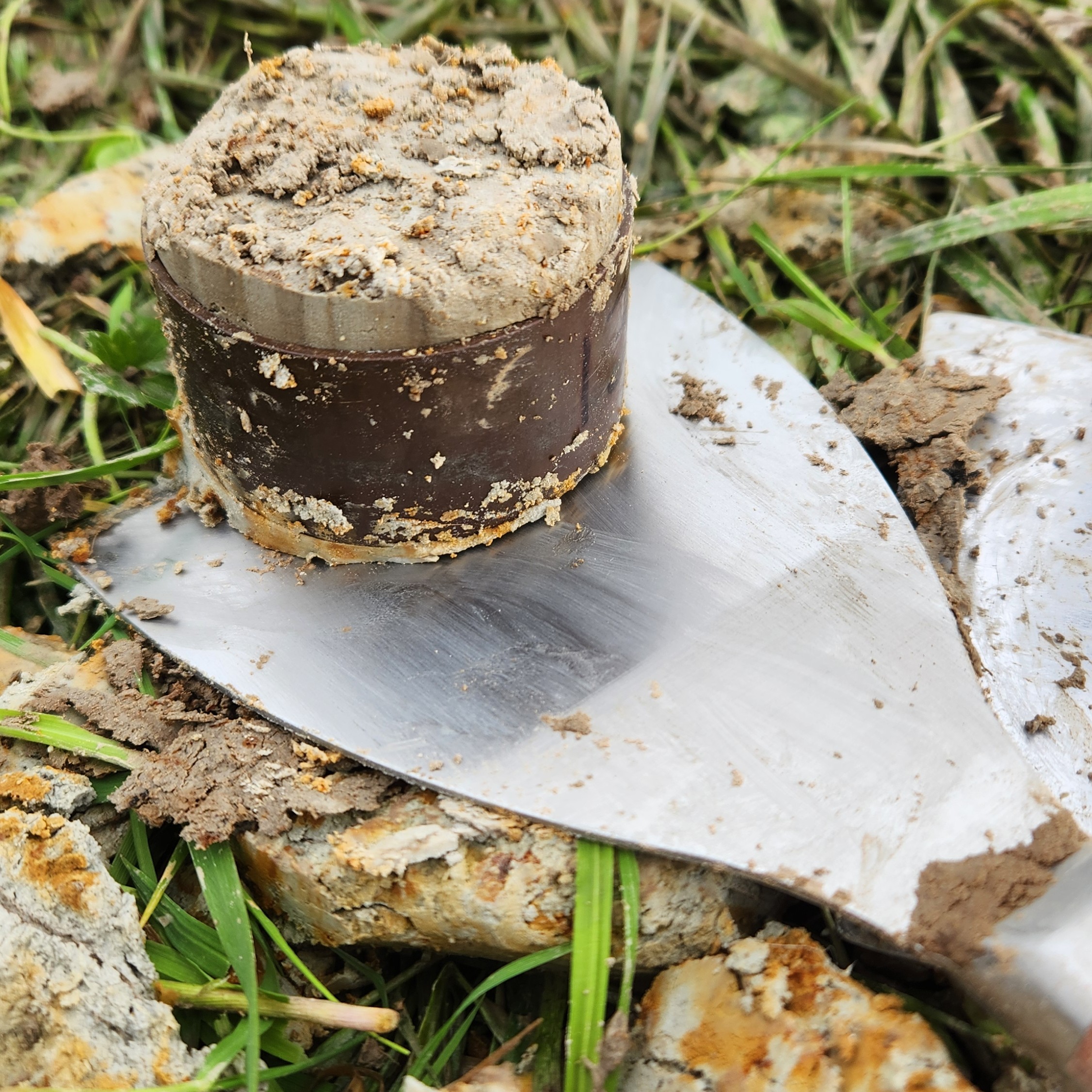
- Using a scraper or knife, make a horizontal slice under the sample, approximately 0.5–1 cm below the bottom edge of the ring. Use the inserted tool to lift the ring and its sample out of the soil.
- Trim the soil from both ends of the sample to leave a flattish surface about 2–5 mm proud of the containing ring. Do not trim down to the very edge of the sampling ring. This helps protect the sample during transportation. Final trimming to length will be carried out in the laboratory.
- Firmly wrap the sample in cling film to prevent drying and to support the sample during transportation. Do not use a bag unless it can be airtight. Store the wrapped sample in a rigid container to protect the top and bottom surfaces during transport.
- Record the profile identifier, horizon number, depth range sampled and ring number on the data recording sheet.
- Cut the pedestal down to the next target depth and repeat.
Smaller sampling rings (e.g. 40 mm x 30 mm) are considered less reliable due to their small volume. When sampling with these, take two samples from each horizon, separated vertically if the horizon thickness allows.
For full-pit sampling, work down one side of the pit face, leaving the other side intact for description and chemical sampling.
Mechanical coring systems (see Section C.1.4) can be used to extract intact soil cores suitable for bulk density determination under the right conditions. Multiple core samples collected from consistent depths are preferred to maximise reliability. For example, New Zealand’s National Soil Carbon Monitoring program samples from ten cores at each monitoring location (Mudge et al. 2025).
C.3.2.2 Bulk density in stony soils
The following method may be applied to mineral soils with appreciable rock fragments no larger than 200 mm (gravel and cobble), and is practical down to a maximum depth of ~60 cm. The method will usually require several hours and is most efficient with two workers involved. The method can be applied on slopes up to 10 degrees and can measure total stone content as well as fine-earth bulk density.
Equipment
- 20 x 20 cm square metal frame with anchors
- Small digging tools
- Robust 10 mm sieve, at least 50 cm diameter
- 2x large trays
- 1 x scale (max weight 20 kg)
- Data recording sheet
- Plastic garbage bags
- Small beads of regular, known, size and weight (0.025 m3 or ~25 L total), stored in buckets with secure lids
- Straight-edged ruler or similar, ~3 cm x 30 cm
- Blunt-edged scoop(s)
Method
- Locate a sampling position and trim any surface vegetation down to the surface over a 30 x 30 cm block.
- Anchor the metal frame inside the trimmed-back area.
- Place a plastic bag over the frame and fill it with beads, using a ruler to level the beads against the frame surface.
- Remove and weigh the beads; record their weight. Place the bag and beads to one side. This measures the ‘headspace volume’.
- With the headspace volume recorded, start excavating inside the frame.
- Remove all soil and stone into a large tray, sieving to separate the >10 mm stone.
- Excavate to a depth of 10 cm, being careful to square up the pit sides and base as accurately as possible.
- Weigh and record the sieved stones.
- Weigh and record the sieved soil (including organic material).
- Collect ~1 kg of the sieved fine soil into a labelled sample bag.
- Line the pit with a plastic bag, and fill the bag with beads, level with the frame surface.
- Extract and weigh the beads.
- Repeat steps 6–12 for each additional 10 cm increment down to 60 cm, or until the gravels become impassable. Soil and beads may have to be weighed in batches.
- If a larger pit is not available for morphology description, describe the soil profile visible within the framed pit, allowing for the limited area and depth.
C.3.3 Composite sampling
Sample composites taken across a site or landform may be necessary for establishing areal average measurements in locally variable properties. Mechanical corers may be used, smaller C1 style corers or even a spade or trowel if only surface soils are being sampled. In either case, use the following method:
- Within the target area for sampling, extract 5–25 small samples to the target depth (e.g. 10 cm, or the local depth of the first horizon).
- Individual sampling points should usually be pre-determined to avoid bias, e.g. spaced out on a grid or transect.
- For some applications, one may wish to deliberately avoid sampling through obviously non-representative materials like cowpats.
- Gather a total mass of 2–10 kg.
- Bag the samples together, clearly labelled as a composite.
- If the total sample volume is very large, place the extracted samples into a bucket or onto a clean tarpaulin and mix to homogenise. Sub-sample the desired volume from the mixture.
C.3.4 Establishing a soil monitoring plot
The following method is an example of a monitoring plot that can be revisited multiple times, sampling undisturbed soil from a small defined area. The example sets up a 20 x 20 m plot, but the concept can be scaled to fit smaller landforms or larger target areas like paddocks.
Other examples of soil monitoring plot designs can be found in NEMS (2022) and Department of Conservation (2024).
Equipment
- 6 corner marking pegs (e.g. pigtail stakes or light waratah posts)
- 10 sample point marking pegs, clearly numbered 1–10
- 1 x 100 m measuring tape
- 1 x 30 m measuring tape (minimum)
- 1 x compass
Method
This method is most easily undertaken by two people, but can be completed alone with appropriate forethought. The method requires two measuring tapes of (minimum) 100 m and 30 m length respectively, along with 6 marker pegs. The longer tape will mark the perimeter of the plot, and the shorter one diagonals from the plot centre to its corners.
- Place a marker peg at plot centre, and anchor the ends of both measuring tapes to the marker.
- Unreeling the 100 m tape, walk north/uphill for 10 m and place another marker. This is the ‘top of plot’ marker.
- Turn right, wrapping the tape clockwise around the marker, and measure out another 10 m. This brings one to the north-east/upper-right corner of the plot, holding a tape that has been unreeled to 20 m. Put down the 100 m reel.
- Walk back to the plot centre and pick up the second tape, measuring out exactly 14.14 m back to the north-east corner.
- At the corner, move the two tapes until both are straight and under light tension, and the 20 m mark on the first tape aligns with 14.14 m mark on the second. This is the north-east corner of the plot, mark it with a new peg.
- Take the 100 m tape and walk south for 20 m. Place a temporary marker, and then move the diagonal tape from the north-east to the south-east corner. Repeat the exercise of tensioning the tapes to locate the corner accurately, this time with the longer tape measuring 40 m.
- Repeat this exercise again at the south-west corner (60 m) and the north-west (80 m). Close the plot by unreeling the longer tape back to the top of plot marker. The tape should now be unwound to 90 m.
- Check that the plot looks correctly square by lining up opposite diagonal corners with the centre marker. All three should be in a straight line.
When a plot is measured out for the first time, use a high-precision GPS to record the position of all markers. Photograph the plot standing back from each corner and looking in towards the centre, capturing nearby features.
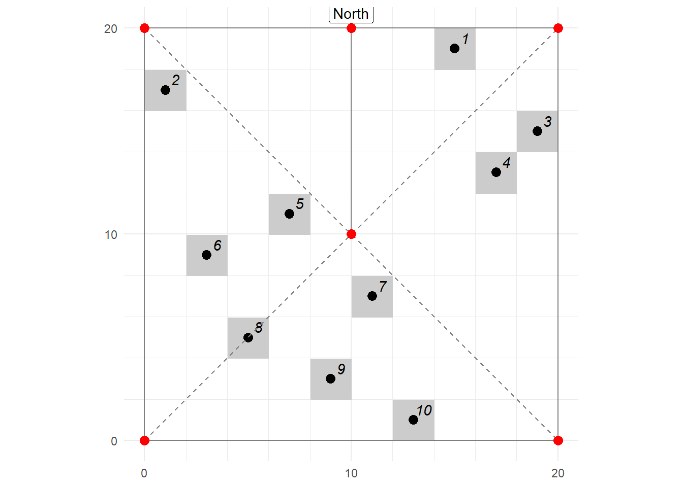
Marking sampling points
The 20 x 20 m plot is divided up into 2 x 2 m ‘cells’. Use a latin-square pattern to pick only one cell per row/column combination, like the one in Figure C.2. Place a numbered marker peg at the centre of each cell.